


Motors Basic. Part Three: Basic Principles – permanent magnet AC motors and motor ratings
In this article we look at the benefits – and disadvantages – of permanent magnet AC motors, how motors are rated, and the impact of starting currents and Power Factors.

Permanent Magnet AC Motors
Like an induction motor, a permanent magnet motor has a Stator configured to provide a number of poles, usually for a 3-Phase supply.
However, instead of containing Rotor bars, the Rotor has magnets mounted on, or embedded in, the laminations. These magnets, which are often made from rare earth elements (neodymium or samarium cobalt), provide a strong permanent magnetic field around the Rotor.
This field reacts with the Stator’s rotating magnets (in the same way as in an induction motor), but there is one important difference: unlike the induction motor, which relies on the rotational slip between the Rotor and Stator magnetic fields to induce a magnetic field in the Rotor, in a permanent magnet motor, the Rotor follows the Stator magnetic field directly. Furthermore, the rotating magnetic field is created by an electronic circuitry which magnetises demagnetising the appropriate motor poles. Thus by altering the timing or pattern of the process, EC motors could vary their speed infinitely and change rotational direction.
Hence, an electronic drive is required to control the operation of a permanent magnet motor. This can be separate – just like a variable speed drive used on an induction motor – or can be integrated into the motor casing, usually on the non-drive end cover.
The international description for permanent magnet motors with integral drives is a ‘Power-Drive System’ (this is the description used by Fläkt Woods); some manufacturers also use the term ‘Electronically Commutated (EC) Motor’.
Benefits of Permanent Magnet AC Motors
Because the Rotor in a PM motor doesn’t require any electrical current, it can be more efficient than an equivalent induction motor, as there will be none of the electrical losses that would be present in an induction Rotor.
This also means the heat generation is reduced, leading to improved reliability and operational life, and reduced maintenance in terms of relubrication.
Because of the permanent magnetic field, the Rotor can generate a higher torque at start-up compared with an induction Motor. The generally stronger magnetic field of the PM Rotor means more torque generated over the whole operating range, giving a higher power output for any given frame size. Thus the same-size motor can be made more powerful, or conversely the motor can be smaller and generate the same power.
This last point is important in ventilation systems, as it means reduced weight and, crucially, improved aerodynamics when the motor is mounted in the airstream.
The presence of an electronic drive provides for variable speed control with no increase in wiring complexity, apart from the provision of a control signal. Some drives including the Fläkt Woods power-Drive System) can use connections from external sensors or networks for intelligent control.
Figure One is a table showing the relative advantages and disadvantages of permanent magnet motors and induction motors.
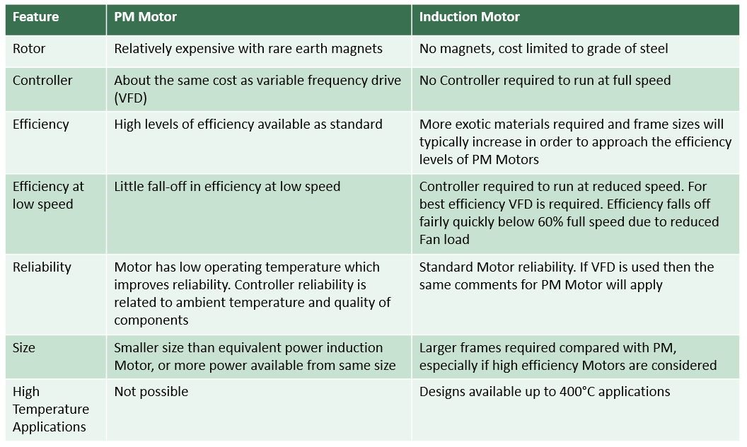
Figure 1: relative advantages and disadvantages of permanent magnet and induction motors
Although the initial cost of permanent magnet motors can be three or four times that of induction motors, this can be offset by the increased efficiency which delivers improved running costs.
So if speed control is required and it is intended to operate mainly at reduced speed to minimise running costs, PM motors do provide cost benefits over induction motors; however, if speed control is not required and running costs are not a primary concern, PM motors’ appeal is not so great – although their compact size and associated reduced weight may be a factor.
It is unlikely that PM motors will be suitable for us in emergency high temperature applications.
The Motor Nameplate
All general purpose motors are required to be shipped with a nameplate, which will contain specific information about the motor.
The IEC standard requires the following information to be provided:
- The manufacturer's name, model and serial number
- Rated voltage and full load amps
- Rated frequency
- Phase
- Rated full load speed
- Rated temperature rise or insulation Class
- Rated ambient temperature
- Duty rating
- Rated kW
- IE rating (efficiency) of Motor
In addition, further information may sometimes be provided on the nameplate:
- Service factor
- Enclosure type
- Frame size
- Connection diagrams
- Unique or special features
Motor Ratings
Motors are rated in terms of their mechanical output power at the shaft, in accordance with IEC 60034-1. The power is specified in terms of Watts (W), but most manufacturers express the power in kW.
The temperature rise of the Stator windings must be within the limit of temperature rise for the motor’s Thermal Class, and is assessed when the motor is operating in its intended use. IEC 60034-1 specifies the limits for operation as being under site operating conditions.
General purpose motors with integral cooling fans will be tested on a dynamometer under the standard ambient conditions (temperature between -15°C and 40°C, and altitude up to 1000 m). This motor rating is described as ‘Totally Enclosed Fan Cooled’ or TEFC.
Motors designed for use when mounted in the airstream of a Direct Drive Fan are tested when installed in the fan. Sometimes a dynamometer may be used with a supplementary fan providing cooling air at the equivalent velocity that would be experienced in the fan; these conditions are referred to as ‘Air Over the Motor’ (AOM) or airstream rated, and the motors are described as ‘Totally Enclosed Air Over’ machines (TEAO).
Generally TEFC rated motors can be used in Direct Drive Fans without adjustment to their rating, (although the direction of the motor fan compared with the main airflow should be considered).
AOM rated motors can only be used when installed in a suitable Direct Drive Fan. If the fan has a low volume flow rate (because of a low blade angle, for example), or if the motor is mounted in a drum or behind a large hub, then a de-rating factor will be required to adjust the motor’s rating accordingly.
Fans installed in Direct Drive Bifurcated Fans must have TEFC motors rated at TEFC conditions.
AOM ratings are typically 10 to 20% higher than TEFC ratings, depending on the design of the motor and the air velocity available from the fan.
Starting Current
When an induction motor is started by connecting directly to the full voltage electrical supply, the instantaneous current drawn will typically be five to seven times higher than the full load current. Known as the ‘Locked Rotor Current’, it is so high because when the Rotor is not turning, the only impedance to the electrical flow comes from the resistance of the Stator windings.
As the Rotor starts to rotate, this impedance also increases, resulting in less electrical current flowing in the Stator windings.
Alternative starting methods such as Variable Frequency Drive (VFD or Inverter), Soft Starter and Star/Delta can reduce this initial starting current.
Induction motors consist of resistive and inductive circuits, and this causes the current waveform to be out of phase with the voltage. The phase difference between the voltage and current waveforms is expressed as a Power Factor (PF). A PF of 1 means that the waveforms are in phase; a PF of less than 1 means that the current is leading or lagging behind the voltage.
The Power Factor can be calculated using the equation:
Power Factor = Active Power
Apparent Power
The Active power is the useful electrical power used by a motor, and is measured in Watts (W). The Apparent power consists of Active Power and Reactive Power, and is measured in volt-amps (VA). That Reactive Power is the power stored in and discharged by a motor, and is measured in volt-amps reactive (VAR).
A Power Factor of less than 1means that the circuit’s wiring has to carry more current than that which would be necessary were the power Factor equal to 1. That could mean that the supply cables and switchgear would need to be sized for a higher rating.
The Power Factor can be improved by selecting a different motor, or if this is not possible, power factor correction capacitors could be installed – although these are expensive and not always practical.