UNDER PRESSURE: THE BASIC PRINCIPLES OF AIR MOVEMENT
This article explains the basic principle of air movement; how creating a pressure differential is the key to creating a flow of air; and how we can measure pressure – the first step in selecting the right fan to provide the desired air flow.

Why Air Flows
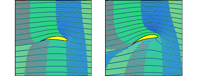
In one respect air is like water – it will naturally flow from an area of high pressure to an area of low pressure. A domestic water system is generally under pressure (usually around 30psi), so when you open a tap, the pressure at that tap falls to zero, which causes water to flow to the low-pressure area.
Air is a fluid, just like water. It will also flow from one area to another because of a difference in pressure. Therefore, to create an airflow, we need to create a pressure differential. A fan causes air movement (or ‘flow’) by creating that pressure differential, causing air to move from the area of high pressure to the area of low pressure.
The amount of air which will flow through a duct, and the speed at which it will flow, are both dependent on the degree of pressure difference which is generated (and by system resistance, or friction). The higher the difference in pressure, the greater quantity of air will flow in a given period of time.
For an Axial flow fan this increase in pressure differential is created by changing the impeller “pitch angle”. The principle therefore is that a higher impeller blade angle will create a greater pressure differential and an associated increase in air flow. It should also be noted that increasing the impeller blade pitch angle will also increase the amount of power needed to drive the impeller.

Understanding these basic principles is the key to selecting the correct fan which will deliver the desired air flow.
Defining Pressure
There are several different terms used in measuring and defining pressure. As they are all inter-related, it is important to be familiar with each term, as well as the units used to measure them.
There are four main factors we need to consider:
- Air Velocity: this is simply the speed of air in a given direction, past a fixed point. It is measured in metres per second (m/s), and is given the symbol ‘v’.
- Volume Flow Rate: this is the amount of air passing a given point in a given unit of time. It is measured in cubic metres per second (m3/s), and is given the symbol ‘qv’. It can also be expressed as the average air velocity multiplied by the area of the measuring plane.
- Static Pressure: this is the pressure which acts equally in all directions, and is the pressure which maintains air movement against a resistance. It is measured in Pascals or Newtons per square metre (Pa or N/m2), and is given the symbol ps, or when a fan is involved, psF.
- Dynamic (or Velocity) Pressure: this is the pressure which is due solely to the speed of the air movement, and it acts in the direction of the air. It is also measured in Pascals (Pa or N/m2), and is given the symbol pd, or when a fan is involved, pdF. Dynamic pressure can be expressed by the formula pdF = 0.5 ρ v2 (where ρ is air density in kg/m3 and v air velocity in m/s).
How They Are Related
From these factors, we can calculate the total amount of energy in the air at a given point, which is known as Total Pressure. Total Pressure is the sum of the Dynamic and Static Pressures (not to be confused with the total sum of the static pressure drops within a ductwork system). Total Pressure is measured in Pascals (Pa or N/m2), and is given the symbol p, or when a fan is involved, pF.
Given that Total Pressure is the sum of Static Pressure and Dynamic Pressure, we can deduce some simple formulae to help understand the relationships between each type of pressure:
- Total = Static + Dynamic, or pF = psF + pdF
- Dynamic = Total – Static, or pdF = pF – psF (where pdF = 0.5 ρ v2)
- Static = Total – Dynamic, or psF = pF - pdF
Measuring Pressure
The most common tool used to measure pressure both on site and in a standardised laboratory condition is a Pitot Tube (also known as a Pitot Probe). Invented by the French engineer Henri Pitot in the early 18th century, it was developed into the form we still use today in the 19th century by Pitot’s compatriot Henry Darcy.
As well as being used to measure liquid, air and gas flows, the Pitot Tube is also widely used to determine the airspeed of aircraft, and the water speed of boats.
A typical Pitot Tube is designed to give us the opportunity to measure the directional component – and therefore the Dynamic Pressure (which as we have seen, acts in the direction of the air). This is important, because it then becomes possible to derive a value for the Total Pressure, by adding the Static Pressure to the Dynamic Pressure, using the above formula.
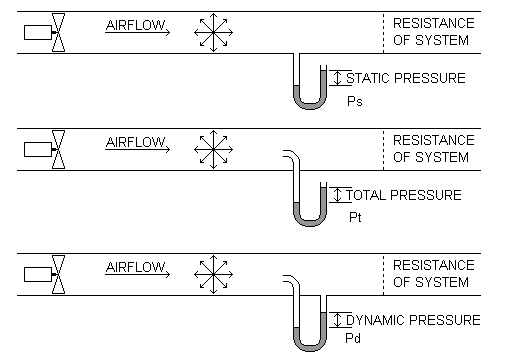
The three types of pressure are measured in slightly differing ways. To measure Static Pressure, a perpendicular tube exits the duct. The tube contains fluid, which is brought to rest (stagnates) as there is no outlet to allow the flow to continue.
Total Pressure is measured in the same way, except that the entry to the tube points directly into the air flow. To measure Dynamic Pressure, the entry to the tube again points into the air flow, but the tube itself has a perpendicular outlet back into the duct.

An alternative method is to use the ‘side tapping’ method, which relies on ‘tapping points’ on the side of the casing or duct. However, this only allows the measurement of Static Pressure. In order to measure Dynamic Pressure (and hence determine Total Pressure), it is first necessary to measure the velocity of the air moving through the fan.
A disadvantage of using a single side pressure tapping method (in a test duct) is that it can be affected by uneven pressure profiles within the system. To minimise this, it is usual for laboratory test ductwork to have multiple ‘side pressure tapping’ positions around the duct, so that an average pressure value can be obtained.